X. GNS3 RÉSEAU N° 8
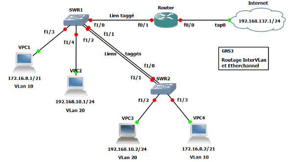
Vous allez créer un réseau constitué d'un routeur et de deux commutateurs (Type Cisco 3725). Le module "NM-16ESW" est installé sur "SWR1" et "SWR2" ; "SWR1" et "SWR2" peuvent être installés avec un disque virtuel PCMCIA de 128 MiB pour sauvagarder vos configurations. Des ordinateurs [VPCx] complètent la topologie pour les tests de fonctionnement.
Figure 65 - RES8 - Topologie réseau n° 8

|
Note |
|---|---|
|
Pour utiliser le disque virtuel PCMCIA de 128 MiB, effecutez les manipualtions suivantes : |
10.1 - Créer la topologie du réseau
Les liens sont les suivants :
Tableau 1 - Liens manuels Cloud, routeur et commutateurs
| Routeurs / Commutateurs | Liens |
|---|---|
| Cloud - Internet | tap0 (Linux) est connecté à [Router] f0/0 |
| Router | f0/0 est connecté à Internet tap0 f0/1 est connecté à SWR1 f1/0 |
| SWR1 | f1/0 est connecté à [Router] f0/1 f1/1 est connecté à SWR2 f1/0 f1/2 est connecté à SWR2 f1/1 f1/3 est connecté à VPC1 f1/4 est connecté à VPC2 |
| SWR2 | f1/0 est connecté à SWR1 f1/1 f1/1 est connecté à SWR1 f1/2 f1/2 est connecté à VPC3 f1/3 est connecté à VPC4 |
10.2 - Connecter et configurer les ordinateurs [VPCx]
Configurez les quatre ordinateurs [VPCx] de la manière suivante :
Tableau 2 - Ordinateurs VPCx
| VPCx | Valeurs |
|---|---|
| VPC1 | LPort:30000 - hôte distant:127.0.0.1 - RPort : 20000 |
| VPC2 | LPort:30001 - hôte distant:127.0.0.1 - RPort : 20001 |
| VPC3 | LPort:30002 - hôte distant:127.0.0.1 - RPort : 20002 |
| VPC4 | LPort:30003 - hôte distant:127.0.0.1 - RPort : 20003 |
Sur le commutateur "SWR1", faites les liens manuels suivants :
Tableau 3 - Liens SW1, VPC1 et VPC2
| VPCx | Liens SWR1 |
|---|---|
| VPC1 | nio_udp:30000:127.0.0.1:20000 ==> f1/3 |
| VPC2 | nio_udp:30001:127.0.0.1:20001 ==> f1/4 |
Sur le commutateur "SWR2", faites les liens manuels suivants :
Tableau 4 - Liens SW2, VPC3 et VPC4
| VPCx | Liens SWR4 |
|---|---|
| VPC3 | nio_udp:30002:127.0.0.1:20002 ==> f1/2 |
| VPC4 | nio_udp:30003:127.0.0.1:20003 ==> f1/3 |
Configurez sur les ordinateurs "VPCx" les adresses IP suivantes :
Tableau 5 - Adressage IP des ordinateurs VPCx
| VPCx | Adresses IP |
|---|---|
| VPC1 - VLAN 10 | IP : 172.16.8.1/21 - GW : 172.16.8.254 |
| VPC2 - VLAN 20 | IP : 192.168.10.1/24 - GW : 192.168.10.254 |
| VPC3 - VLAN 20 | IP : 192.168.10.2/24 - GW : 192.168.10.254 |
| VPC4 - VLAN 10 | IP : 172.16.8.2/21 - GW : 172.16.8.254 |
|
|
Note |
|---|---|
|
Pour configurer un DNS, vous pouvez taper la commande suivante sur chaque [VPCx] : |
Sauvegardez la configuration de vos "VPCx" :
VPCS[1]>save res8.vpc......... done
10.3 - Configurer les commutateurs SWR1 et SWR2
Démarrez tous les appareils puis Lancez les "consoles".
Configuration de "SWR1" :
Router>enRouter#conf tEnter configuration commands, one per line. End with CNTL/Z.Router (config)#hostname SWR1SWR1(config)#line con 0SWR1(config-line)#logging synchronousSWR1(config-line)#exitSWR1(config)#vlan 10SWR1(config-vlan)#name IngenierieSWR1(config-vlan)#exitSWR1(config)#int f1/3SWR1(config-if)#switchport mode accessSWR1(config-if)#switchport access vlan 10SWR1(config-if)#no shutSWR1(config-if)#exitSWR1(config)#vlan 20SWR1(config-vlan)#name CommerciauxSWR1(config-vlan)#exitSWR1(config)#int f1/4SWR1(config-if)#switchport mode accessSWR1(config-if)#switchport access vlan 20SWR1(config-if)#no shutSWR1(config-if)#exitSWR1(config)#int f1/0SWR1(config-if)#speed 100SWR1(config-if)#duplex fullSWR1(config-if)#switchport mode trunkSWR1(config-if)#switchport trunk encapsulation dot1qSWR1(config-if)#switchport trunk allowed vlan add 10,20SWR1(config-if)#no shutSWR1(config-if)#exitSWR1(config)#int f1/1SWR1(config-if)#switchport mode trunkSWR1(config-if)#switchport trunk encapsulation dot1qSWR1(config-if)#switchport trunk allowed vlan add 10,20SWR1(config-if)#channel-group 1 mode onSWR1(config-if)#no shutSWR1(config-if)#exitSWR1(config)#int f1/2SWR1(config-if)#switchport mode trunkSWR1(config-if)#switchport trunk encapsulation dot1qSWR1(config-if)#switchport trunk allowed vlan add 10,20SWR1(config-if)#channel-group 1 mode onSWR1(config-if)#no shutSWR1(config-if)#exitSWR1(config)#int port-channel 1SWR1(config-if)#switchport mode trunkSWR1(config-if)#switchport trunk encapsulation dot1qSWR1(config-if)#switchport trunk allowed vlan add 10,20SWR1(config-if)#no shutSWR1(config-if)#endSWR1#write memBuilding configuration...[OK]SWR1#copy run startDestination filename [startup-config]?Building configuration...[OK]
Configuration de "SWR2" :
Router>enRouter#conf tEnter configuration commands, one per line. End with CNTL/Z.Router (config)#hostname SWR2SWR2(config)#line con 0SWR2(config-line)#logging synchronousSWR2(config-line)#exitSWR2(config)#vlan 10SWR2(config-vlan)#name IngenierieSWR2(config-vlan)#exitSWR2(config)#int f1/3SWR2(config-if)#switchport mode accessSWR2(config-if)#switchport access vlan 10SWR2(config-if)#no shutSWR2(config-if)#exitSWR2(config)#vlan 20SWR2(config-vlan)#name CommerciauxSWR2(config-vlan)#exitSWR2(config)#int f1/2SWR2(config-if)#switchport mode accessSWR2(config-if)#switchport access vlan 20SWR2(config-if)#no shutSWR2(config-if)#exitSWR2(config)#int f1/0SWR2(config-if)#switchport mode trunkSWR2(config-if)#switchport trunk encapsulation dot1qSWR2(config-if)#switchport trunk allowed vlan add 10,20SWR2(config-if)#channel-group 1 mode onSWR2(config-if)#no shutSWR2(config-if)#exitSWR2(config)#int f1/1SWR2(config-if)#switchport mode trunkSWR2(config-if)#switchport trunk encapsulation dot1qSWR2(config-if)#switchport trunk allowed vlan add 10,20SWR2(config-if)#channel-group 1 mode onSWR2(config-if)#no shutSWR2(config-if)#exitSWR2(config)#int port-channel 1SWR2(config-if)#switchport mode trunkSWR2(config-if)#switchport trunk encapsulation dot1qSWR2(config-if)#switchport trunk allowed vlan add 10,20SWR2(config-if)#no shutSWR2(config-if)#endSWR2#write memBuilding configuration...[OK]SWR2#copy run startDestination filename [startup-config]?Building configuration...[OK]
Sauvegardez le projet :
Menu[Fichier] de GNS3 => [Sauvegarder]
10.4 - Configurer l'équilibrage de charge
Pour configurer l'équilibrage de charge sur "SWR1", tapez les commandes suivantes :
SWR1>enSWR1#conf tEnter configuration commands, one per line. End with CNTL/Z.SWR1(config)#port-channel load-balance src-dst-ipSWR1(config)#endSWR1#write memBuilding configuration...[OK]SWR1#copy run startDestination filename [startup-config]?Building configuration...[OK]
Sauvegardez le projet :
Menu[Fichier] de GNS3 => [Sauvegarder]
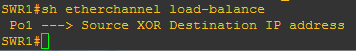
Pour visualiser la configuration de l'équilibrage de charge, tapez la commande "sh etherchannel load-balance".
Figure 68 - RES8 - load-balance
10.5 - Configurer le routeur [Router]
Configuration de "Router" :
Router>enRouter#conf tEnter configuration commands, one per line. End with CNTL/Z.Router(config)#hostname RouterRouter(config)#line con 0Router(config-line)#logging synchronousRouter(config-line)#exitRouter(config)#int f0/0Router(config-if)#ip address 192.168.137.254 255.255.255.0Router(config-if)#no shutRouter(config-if)#exitRouter(config)#ip route 0.0.0.0 0.0.0.0 192.168.137.1Router(config)#int f0/1Router(config)#speed 100Router(config)#duplex fullRouter(config-if)#no ip addressRouter(config-if)#no shutRouter(config-if)#exitRouter(config)#int f0/1.10Router(config-subif)#encapsulation dot1Q 10Router(config-subif)#ip address 172.16.8.254 255.255.248.0Router(config-subif)#exitRouter(config)#int f0/1.20Router(config-subif)#encapsulation dot1Q 20Router(config-subif)#ip address 192.168.10.254 255.255.255.0Router(config-subif)#endRouter#write memBuilding configuration...[OK]Router#copy run startDestination filename [startup-config]?Building configuration...[OK]
Sauvegardez le projet :
Menu[Fichier] de GNS3 => [Sauvegarder]
10.6 - Les commandes utiles
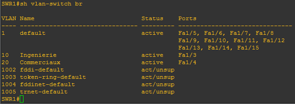
Pour afficher la configuration des VLans, utilisez la commande : sh vlan-switch br.
Exemple sur "SWR1" :
SW1>enSW1#sh vlan-switch br
Figure 66 - RES8 - Commande : sh vlan-switch br
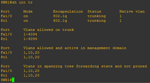
Pour afficher les liens "trunkés", utilisez la commande : sh int trunk.
Exemple sur "SWR1" :
SW1>enSW1#sh int trunk
Figure 67 - RES8 - Commande : sh int trunkr
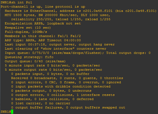
Pour vérifier la configuration de l'Etherchannel, utilisez la commande : "sh int port-channel 1".
Exemple sur "SWR1" :
SW1>enSW1#sh int Po1
Figure 69 - RES8 - Commande : sh int port-channel 1
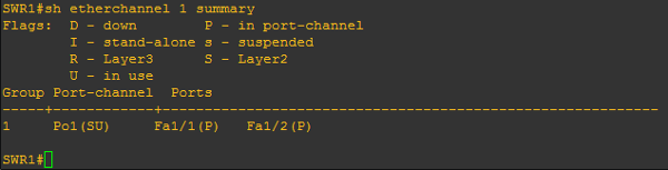
Pour vérifier le fonctionnement de l'etherchannel, tapez la commande : "sh etherchannel 1 summary".
Exemple sur "SWR1" :
SW1>enSW1#sh etherchannel 1 summary
Figure 70 - RES8 - Commande : sh etherchannel 1 summary
10.7 - Tester le fonctionnement de la topologie réseau
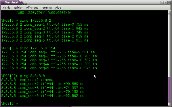
À partir de l'ordinateur "VPC1", tapez les commandes suivantes : "ping 172.16.8.2" puis "ping 172.16.8.254" ; testez l'accès au dns de "google" : "ping 8.8.8.8".
Figure 62 - Commandes ping
À partir de l'ordinateur "VPC2", tapez les commandes suivantes : "ping 192.168.10.2" puis "ping 192.168.10.254" ; testez l'accès au dns de "google" : "ping 8.8.8.8".
Figure 63 - Commandes ping
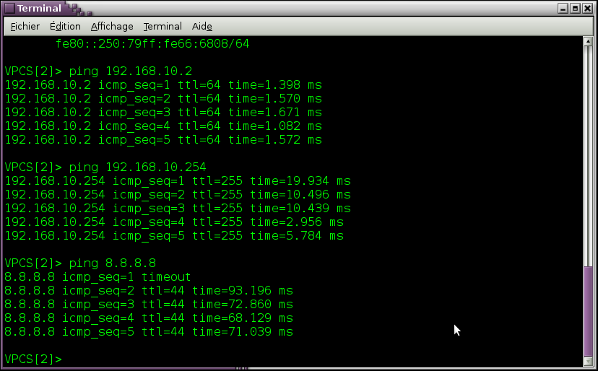
Tout fonctionne, y compris l'accès à l'extérieur.